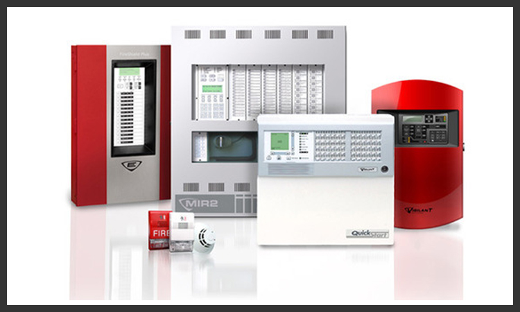
Addressable Fire Detection
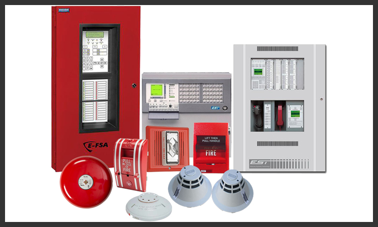
Addressable Fire Detection System is usually more advanced than their conventional Fire Systems, with greater information capacity and control flexibility. Addressable fire alarm panels were introduced by many manufacturers during the microcontroller boom.
Addressable Fire Alarm Control Panel employ one or more Signaling Line Circuits usually referred to as loops or SLC loops ranging between one and thirty. Depending on the protocol used, a Signaling Line Circuit can monitor and control several hundred devices. Some protocols permit any mix of detectors and input/output modules, while other protocols have 50% of channel capacity restricted to detectors/sensors and 50% restricted to input/output modules. Each SLC polls the devices connected, which can number from a few devices to several hundred, depending on the manufacturer. Large systems may have multiple Signaling Line Circuits.
Each device on a SLC has its own address, and so the panel knows the state of each individual device connected to it. Common addressable input (initiating) devices include.
Also known as "cause and effect" or "programming", mapping is the process of activating outputs depending on which inputs have been activated. Traditionally, when an input device is activated, a certain output device (or relay) is activated. As time has progressed, more and more advanced techniques have become available, often with large variations in style between different companies.
Conventional Fire Detection
Conventional panels have been around ever since electronics became small enough to make them viable. Conventional panels are used less frequently in large buildings than in the past, but are not uncommon on smaller projects such as small schools, stores, restaurants, and apartments.
A conventional Fire Alarm Control Panel employs one or more circuits, connected to sensors (initiating devices) wired in parallel. These sensors are devised to dramatically decrease the circuit resistance when the environmental influence on any sensor exceeds a predetermined threshold. In a conventional fire alarm system, the information density is limited to the number of such circuits used.
To facilitate location and control of fire within a building, the structure is subdivided into definite areas or zones. Floors of a multistory building are one type of zone boundary.
An Initiating Device Circuit connected to multiple devices within the same "zone" of protection, effectively provides 2 bits of information about the zone corollary to the state of the circuit; normal, or off normal and alarm or quiescent. The state of each Initiating Device Circuit within a zone displays at the Fire Alarm Control Panel using visible indications called Annunciators.
These Annunciators may employ a graphical representation of the Zone boundaries on a floor plan (Zone map) using textual descriptions, illuminated icons, illuminated sections, or illuminated points on the map corresponding to Initiating Circuits connected to the Fire Alarm Control Panel.
For this reason, slang often inaccurately refers to initiating circuits of a Fire Alarm Control Panel as Zones.
Larger systems and increasing demand for finer diagnostic detail beyond broad area location and control functions expanded the control by Zone strategy of conventional systems by providing multiple initiating circuits within a common Zone, each exclusively connected to a particular type of initiating device, or group of devices. This arrangement forms a device type by Zone matrix whose information is particularly suited to the Tabular Annunciator In multistorey buildings employing a Tabular Annunciator for Example; rows of indicators define the floors horizontally in their stacked relationship and the type of device installed on that floor displays as columns of indicators vertically aligned through each floor. The intersection of the floor and device indicators provides the combined information. The density of information however remains a function of the number of circuits employed.
Even larger systems and demands for finer diagnostic and location detail led to the introduction of addressable fire alarm systems with each addressable device providing specific information about its state while sharing a common communication circuit. Annunciation and location strategies for the most part remain relatively unchanged.
Multiplex systems – Semi Addressable System
Multiplex systems, a sort of transition between conventional and modern addressable systems, were often used in large buildings and complexes from the mid to late 1970s into the late 1980s. Early on, these systems were programmed to function as large conventional systems. Gradually, later installations began to feature components and features of modern addressable systems. These systems were often capable of controlling more than a building's fire alarm system (i.e. HVAC, security, electronic door locks...) without any type of alarm or trouble condition present. While the main panel was the brains of the system and could be used to access certain functions, fire alarm controls were usually accessed through transponders. These were smaller conventional panels programmed to 'communicate' the status of part of the system to the main panel and also could be used to access basic fire alarm control functions.